So I’m back from Brighton, 5 hours of travelling each way and 2 hours of queuing was definitely worth it for front row seats and a prime view of a cat that really wanted to be a part of the show, but that’s not what you came here to read about, so let’s look again at the Magnet system.
One thing that is always good to have when emulating a system are high quality pictures of the board. Arcadehacker provided these along with the dumps and a whole bunch of other information which was helpful in getting things up and running. Let’s have a look at the basic hardware of the Magnet System (click on images for better resolution)
The system uses 5 main PCBs in the cage, so let’s start with a quick view of each layer
1st Layer (Sound)
The top layer is the sound board. This contains a Z80 CPU, 2 Z80CTC peripheral chips (timers / interrupt generators), 2 AY 8910 sound chips and an OKI M5205 ADPCM playback chip for a single channel of sampled sound.

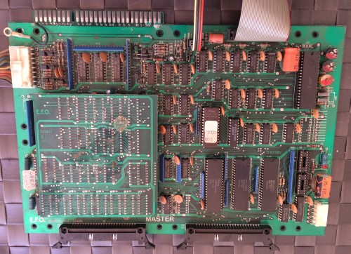
2nd Layer (Master)
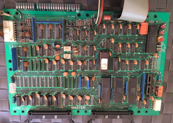
The 2nd PCB is the master board, this board drives everything else. It contains a Z80 CPU, the BIOS rom, 2 Z80 PIO peripheral chips (used for configurable I/O ports) and a SAB 2797B (floppy drive controller) The Floppy drive also connects to this PCB. There’s also a small sub-board on here covering some of the PCB, this contains a selection of RAM chips, I’ll look at it in more detail later.
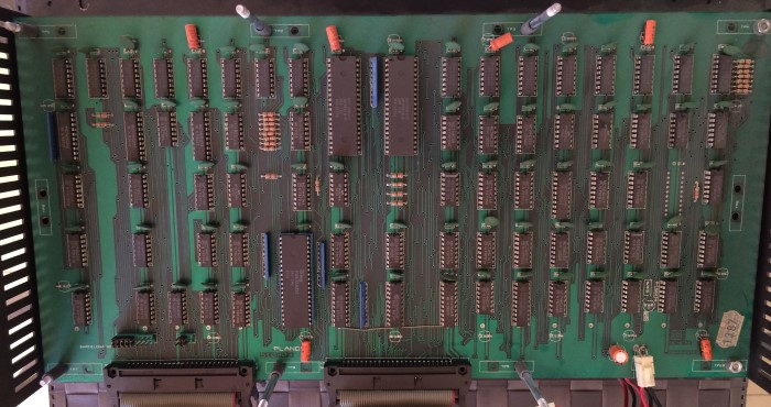
3rd Layer (Plane PCB A)
The 3rd PCB is a ‘Plane’ board, it is used to generate a single background plane. Hardware-wise the main components are yet another Z80 CPU, and like the Master PCB, 2 Z80 PIO peripheral chips.
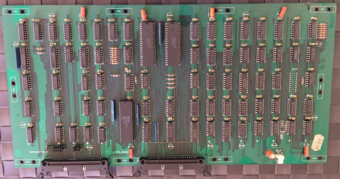
4th Layer (Plane PCB B)
The 4th PCB is another ‘Plane’ board, identical to the 3rd PCB. The only difference here is some jumper configuration.
5th Layer (Sprite PCB)
The Sprite PCB sits at the bottom of the stack. Again we have a Z80, bringing our total Z80 count to 5 (one for each PCB) and this time we have 3 Z80 PIO chips (bringing out total count of those up to 9) There’s also a memory sub-board, which again contains RAM.
Holding it all together
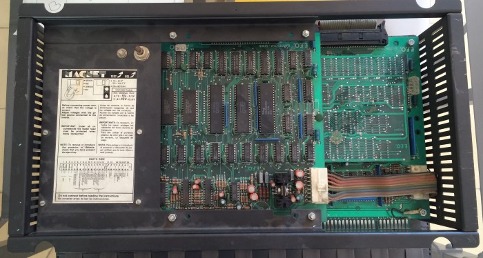
Ribbon cables are the main way the boards are connected, as you can see from the following front/back/above views of the stack.


The Drive
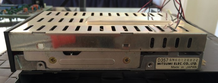
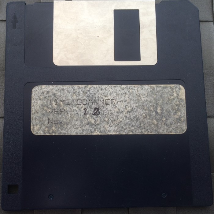
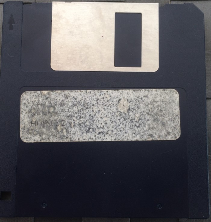
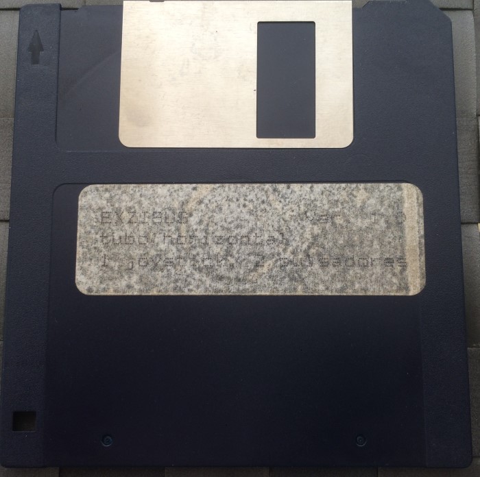
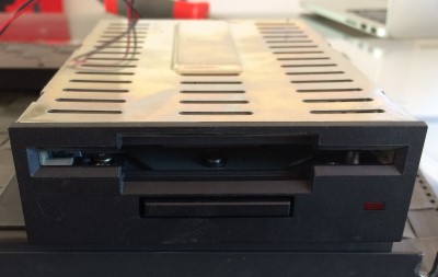
The drive is a Mitsumi drive, there’s also an amusing warning on the panel above it telling you not to put Magnets near the Magnet system disks.

Master Board – More Detail
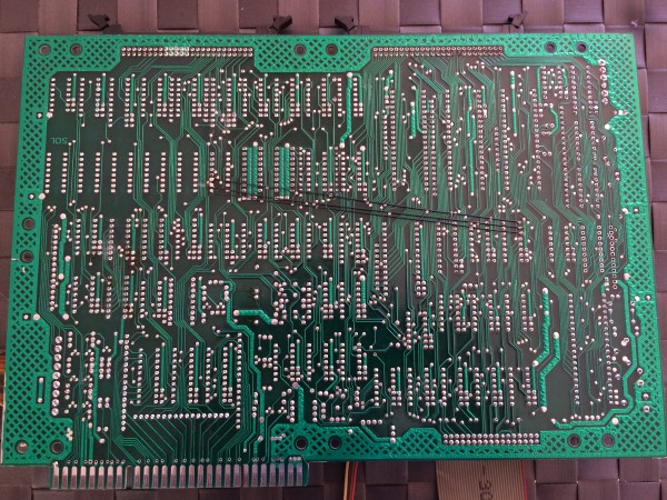
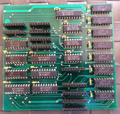
The Top board / Sound board in the initial pictures was obscured by the memory sub-board, so here are some cleaner pictures of both the board, the underside of the board, and the memory sub-board. It’s interesting to note that there is a wire mod on the back of the board.
More interesting however is the memory sub-board which contains
1.5kbytes of memory in the form of 3x MOTOROLA MM2114N SRAM 4096 bit (4x1024bit each)
and
256kbytes of memory in the form of 8x SIEMENS HYB 41256-15 AA – 262,144 bit DRAM (32kbytes each)
These plug into the PCB where presumably memory chips would have originally been fitted, presumably offering a memory expansion over the initial base design.
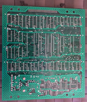
Sound / Plane Boards – Undersides
The Sound board and Plane boards have unremarkable undersides, there are no mods, and nothing was obscured by any memory sub-boards on the top views, so not much to show here.
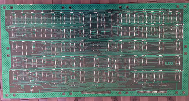
Sprite PCB – more detail
The Sprite PCB was another with a memory sub-board. Like the one on the main board this sub-board contains 256KB of RAM, and appears to plug into the sprite board where regular RAM chips would have been places. In this case it definitely looks like an afterthought because there are wires soldered directly from the board to pins on one of the PIO chips as well as another chip on the PCB. There is also some glue holding it in place, meaning it more difficult to remove, so no clean PCB shot for this one. There is a small mod to the back of the sprite board too.
Hardware Conclusion
5 Z80s, 9 Z80 PIO chips, 2 Z80 CTC chips, AY 8910s, an OKI M5205 and a floppy drive controlled by a SAB 2797B are the main features to note on this hardware. Also a fair amount of RAM, especially when you take all the extra memory on the plug-in boards into account. There are no known dedicated video chips on the PCB so everything is done with the logic you see.
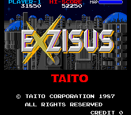
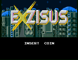
Compared to the hardware the games that were ported run on the only thing that, on the surface, appears remotely close is Exzisus which had a 4x Z80 based setup, however in reality even the Exzisus hardware is very, very different to this, as I would find when I started to emulate it.
